image 1: Traction Elevators.
Division 14 - Conveying Systems
Section 14210 Electric
Traction Passenger Elevators
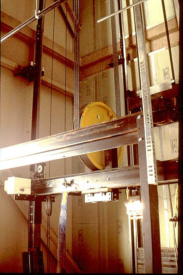
image 1: Traction Elevators.
The view is of the top of a car frame without the finished car enclosure. The car frame is adjusted to run between floors by the elevator installers who must guarantee that all clearances and code requirements are complied with. Elevator adjustments are continued throughout the installation up to final inspection of the conveying system.
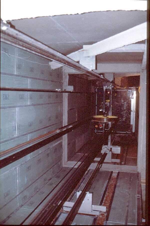
image 2.
Image 2 shows a view down a typical shaft way which goes through the entire building. The shaft way is closed in and fire protected by special gypsum board construction. The gypsum board used here is fire rated and is set in special floor channels to maintain its integrity throughout the shaft. Note the connection of elevator rails to the steel superstructure of the building.
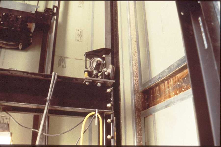
image 3.
Image 3 shows a typical guide wheel truck assembly at a vertical rail. Note the spring loaded mechanical armature which provides a constant pressure on the guide rails and is self adjusting once the car platform it is plumbed.
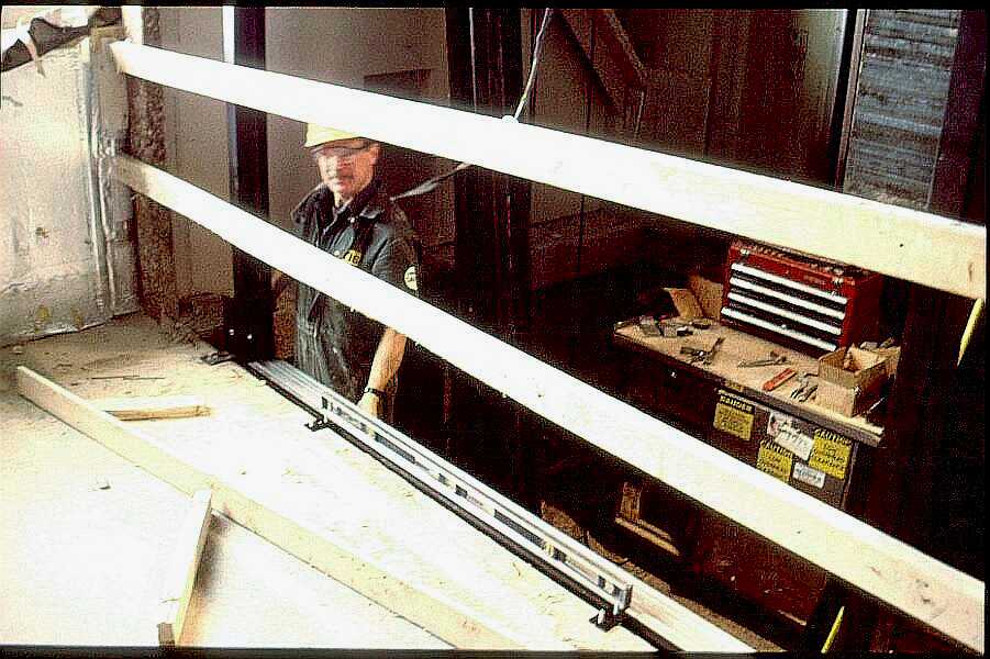
image 4.
Image 4 shows an elevator installer working at the floor slab aligning the cab floor and receiving saddle. Clearances throughout the shaft way are exacting and established by code. To assure a proper dimensional control of the gap between the car floor and the receiving saddle, saddles are always set by the elevator installer and not inserted into the floor slab pour. Note the safety harness worn by the installer to prevent accidental falls. Also note the temporary protection at each opening including a 4" kick board at the floor.
Division 14
Page 1
Copyright ©2001
_____________
URL:
http://__________________/D14-1.htm