
image 1: Underground Piping.
Division 15 - Mechanical
Section 15070 Underground
Piping
image 1: Underground Piping.
This series of images (1-4) show the installation of piping which is buried under slabs and/or at the exterior of the building foundation. The section deals with different types of piping materials, connection specifications, thrust blocks (concrete blocks placed at critical joints in underground piping) , testing and controlled backfill at pipes.
Image 1 shows a footing drain of perforated PVC pipe which has a branch run , shown here under an interior slab on grade. The slab required a sub drainage system due to its lower elevation within the substructure. The footing drains on this building all connect up to a central cistern for controlled evacuation of site storm and underground water.
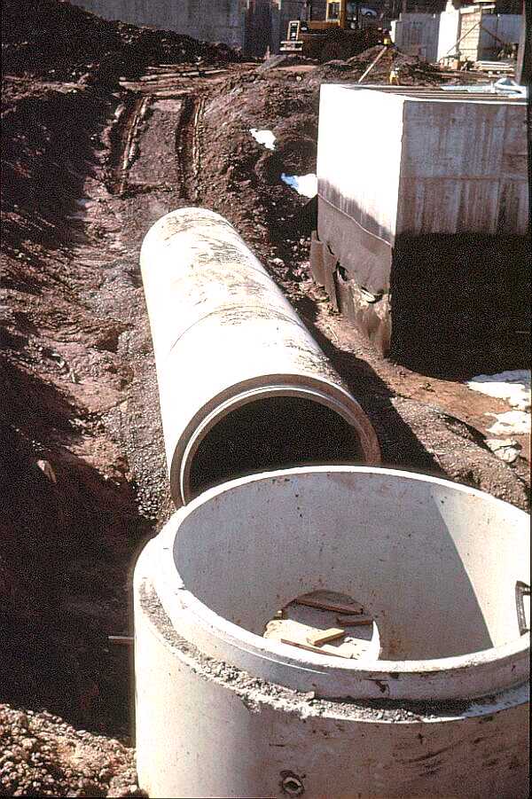
image 2.
View 2 shows precast concrete pipe and catch basin collectors being installed. This is the main cistern for the collection of all site and roof storm water. Note the controlled backfill under the pipe.
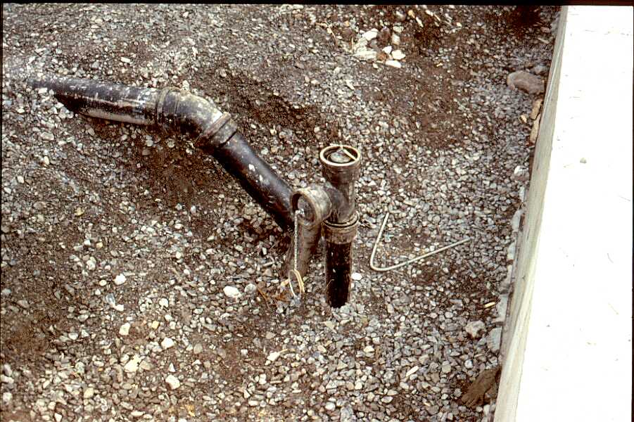
image 3.
Image 3 shows typical underground soil piping with temporary plugs installed to prevent debris from entering the system and provide plugs for pressure testing the underground lines prior to backfill operations.
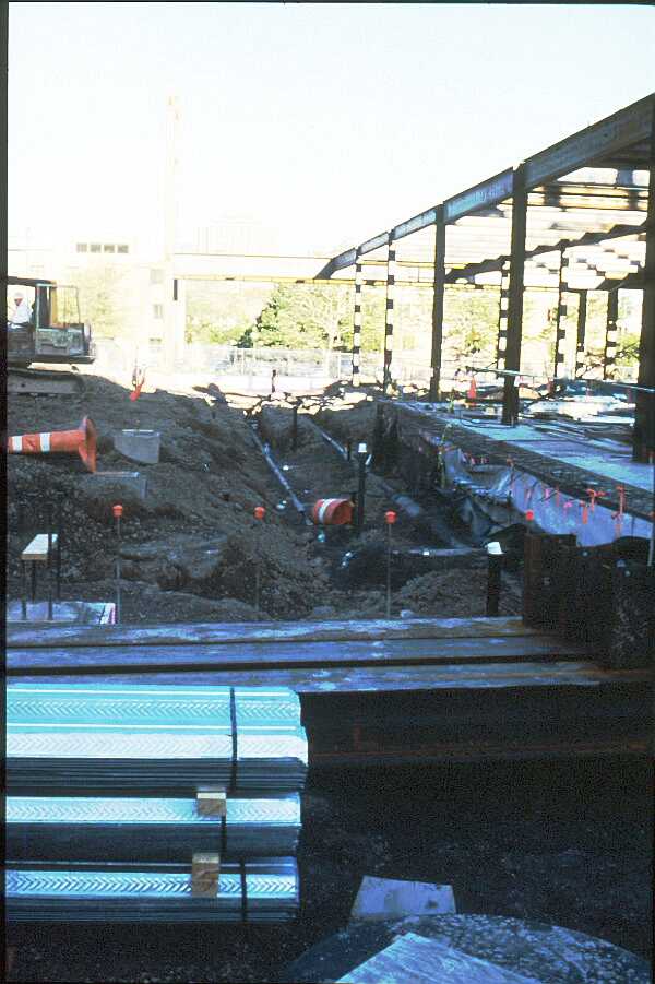
image 4.
Image 4 shows extensive underground soil lines set in controlled backfill. All underground lines must meet a pressure test with a specified static head prior to complete backfill operations. Note the temporary protection at open pipe ends and rebar dowels.
Division 15
Page 1
Copyright ©2001
_____________
URL:
http://__________________/D15-1.htm