image 8: Drilling excavation procedure for caissons.
Division 2 - Site Work
Section
02300- Caisson Operations
image 8: Drilling
excavation procedure for caissons.
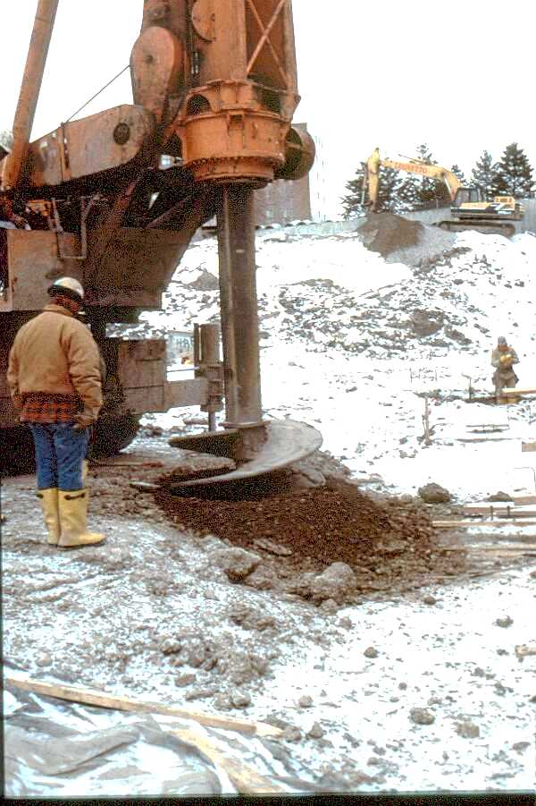
The subsurface investigation performed in Division-1, General Requirements indicated a poor bearing condition for the existing soil which necessitated the installation of caisson to bedrock bearing. The existing underlay of bedrock was within 40 to 60 ft of the bottom of the general site excavation. The bedrock was found to have a bearing capacity which met or exceeded the soil bearing capacity required by the structural engineer for the combined dead and live load of the building. The installation of caissons was therefore required prior to the placement of footings, grade beams, and slabs. The caissons selected were circular concrete, field placed in drilled holes up to 8 ft in diameter. The holes were unlined and were drilled to refusal (bedrock in this instance). The holes maintained their structural integrity without liners due to the cohesive soil condition. The concrete was placed immediately following the drilling procedure and therefore countered any creep, which would occur in the cohesive soil over time. Due to the ambient 50 degree temperature of the sub-surface excavation, winter concrete procedures were not required.
Image 8 shows an initial set up and pilot drill. The drill bits will be increased in size as the excavation progresses. The hole is maintained in a plumb attitude by aligning the drilling machine with optical and/or laser levels. The location of all caissons are carefully sized and centered on a caisson layout drawing which must be approved by the structural engineer. Layout occurs off the base line and monument established and maintained throughout the construction process as a part of the work in Division 1.
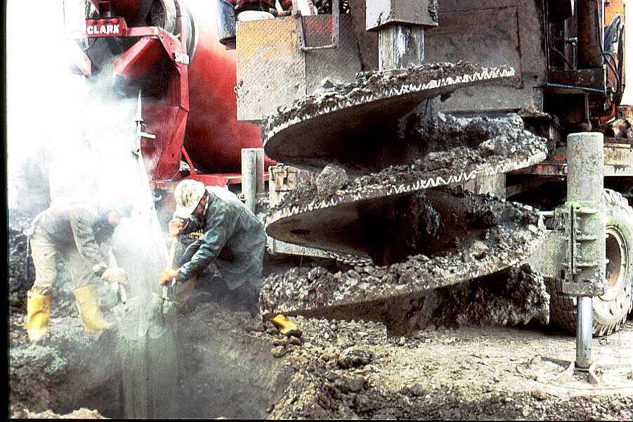
image 9: Placing the concrete caisson.
Image 9 shows the start of concrete placement into the drilled caisson. Note the larger drill bit with indications of drilled rock present as refusal was achieved. The time between final drilling and concrete placement is kept to within minutes of field approval of the caisson bottom bearing condition. This approval is conducted in the field by a soils engineer who is licensed and has experience in such operations.
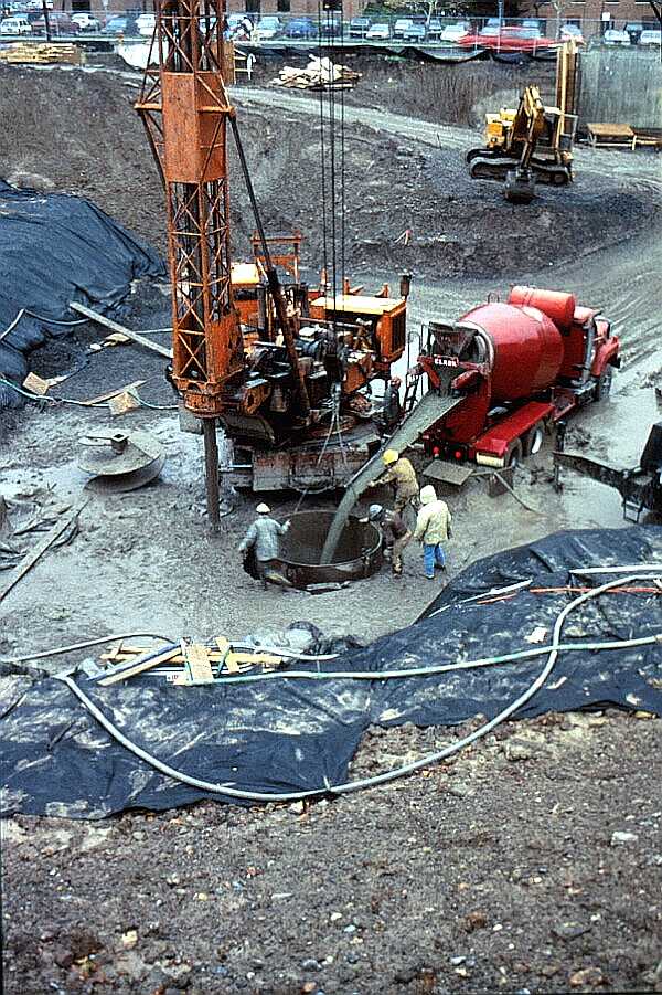
image 10: Tremie placement of concrete through standing
water.
Image 10 shows concrete being placed, using a tremie tube, directly through standing water. Note the dewatering pipes which maintain the water level at the bottom of the proposed substructure but not at the deeper levels of caisson excavation. Concrete will cure under water and the displaced standing water is in turn pumped out of the caisson hole. Filter fabric further prevents soil from entering the caisson excavation from the adjacent benched excavation.

image 11: Caisson concrete placement evaluation.
Image 11 shows concrete in the caisson hole being checked for depth in order to calculate the volume of additional concrete necessary to complete the placement of the caisson to the designed elevation. This is accomplished by a simple string and plumb, which is dropped to the top of concrete.
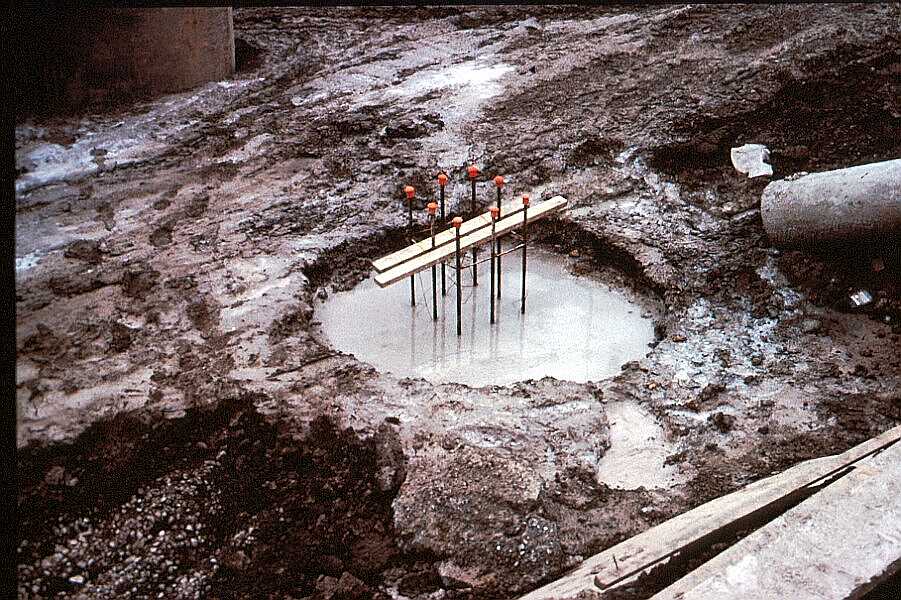
image 12: Completed concrete caisson.
The caisson here (image 12) is completed with steel dowels placed to receive the column footing which will be eventually placed on top. The top of the caisson is therefore the bottom of the column footing as it appears on the structural drawings. Note the orange caps placed on the dowels as a safety measure. The concrete in the caissons was placed during the winter with no frozen conditions present due to the deep excavation through soil with an ambient temperature of 50 to 60 degrees F. The concrete was therefore left to cure under almost an ideal controlled condition. Tests of the field cured caisson showed the concrete achieving its design strength within a 28 day period.
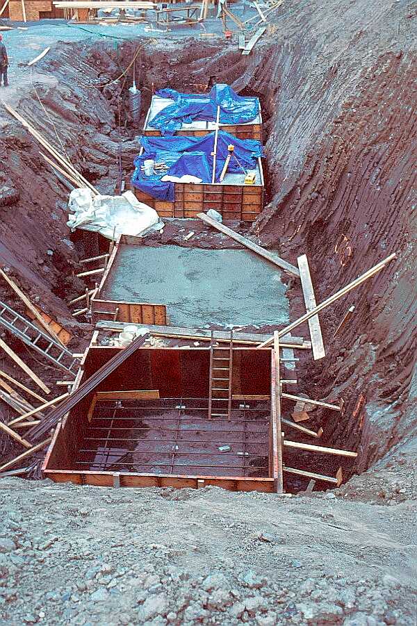
image 13: Footings over caisson bearing.
Image 13 shows deep footings being placed over the caissons. The caissons, in effect, have become the "new" approved bearing material for the building to sit upon. Loads are transferred from footing bottoms, through caissons, to approved bed rock bearing below. All unsuitable bearing material is therefore left in place and/or spanned across.
Division 2
Page 5
Copyright ©2001
_____________
URL:
http://__________________/D2-5.htm